
1971 Triumph Spitfire Rebuild.
Construction notes for Truimph Spitfire Jaeger Mechanical Tachometer Conversion to Electronic.
As stated previously, the object was to create an electronic tachometer where only a mechanical one was available and
to preserve the original appearance. This was an experiment on my part. It is one of the experiments that did work. I do consider this a prototype.
A typical but failed Jaeger Tachometer was used from a 1971 Triumph Spitfire. Carefully disassembling and preserving the original face plate
and dial pointer is crucial. Use some paper towel or something similar as a cushion on the face plate to prevent marring and use a common kitchen
fork to gently pry the pointer off the mechanism. Once that has been removed, place in a plastic bag or similar to protect it.
Using a jewelers screwdriver, very carefully remove the screws holding the face plate to the mechanism. Store these parts in a plastic bag as well.
If the screws are rusty: STOP! Apply some penetrating oil to the screws and let sit for a day or two. If the paint on the face plate or dial, is in good shape,
good enough to be used then the oil should not bother it. Use only enough oil as dispensed by a syringe to the rear / threads of the screw.
If the heads of the screw are rusty as well, apply a minimal amount to them as well.
Disassembling with care will lead to a better looking end product.
The adaptor plate made was from 1/8 inch aluminum stock, type 6061 I believe, a free machining type. It is not that soft junk stuff sold in the big box stores.
The adaptor plate is determined solely by the gauge motor chosen. The adaptor plate supports the tachometer dial, which is supported by the
tachometer gauge motor, which is supported by the glass epoxy circuit board. The circuit board is mounted on some very solid stand off spacers from the rear of the tachometer case.
This follows the same construction layer as the original tachometer with the exception that the components are in the order or 10
or more times lighter. If using a good G10 glass epoxy circuit board with 2 oZ copper, mechanical issues can be avoided. This is very stable, strong board material.
We have the ability to design and etch circuit boards, so we designed our own prototype and then designed a board that is in the car now.
The gauge "motor" was salvaged from a Volvo 850 instrument cluster. Most of the gauge motors of that period and much later will be the same electrically.
They are about 200 to 230 ohms per winding, making them ideal for a number of different drivers..
Other Criteria: No Way.. No How... was a 1971 Triumph Spitfire to be fitted with microprocessor based instruments. Analog technology was not that great at the time.
So a compromise... jump ahead about 20 years into the 1990's. Several chips are available and the ever popular 555 timer circuit for frequency to voltage conversion. But
something simpler was desired. This would be something stand alone... no micro or buss technology, and something that could drive a two phase gauge motor.
It also had to be something inexpensive. The down side to this criteria was no processor or bus. There are tons of chips reliant on CAN bus or other technologies. There
are a few that are not, however manufacturing of these has stopped due to the influx of unnecessary technology in today's automobiles. Well.... In my opinion.
Most of it is wasted junk costing unnecessary dollars in the name of a creature comfort. (However car manufacturers define it......)
|
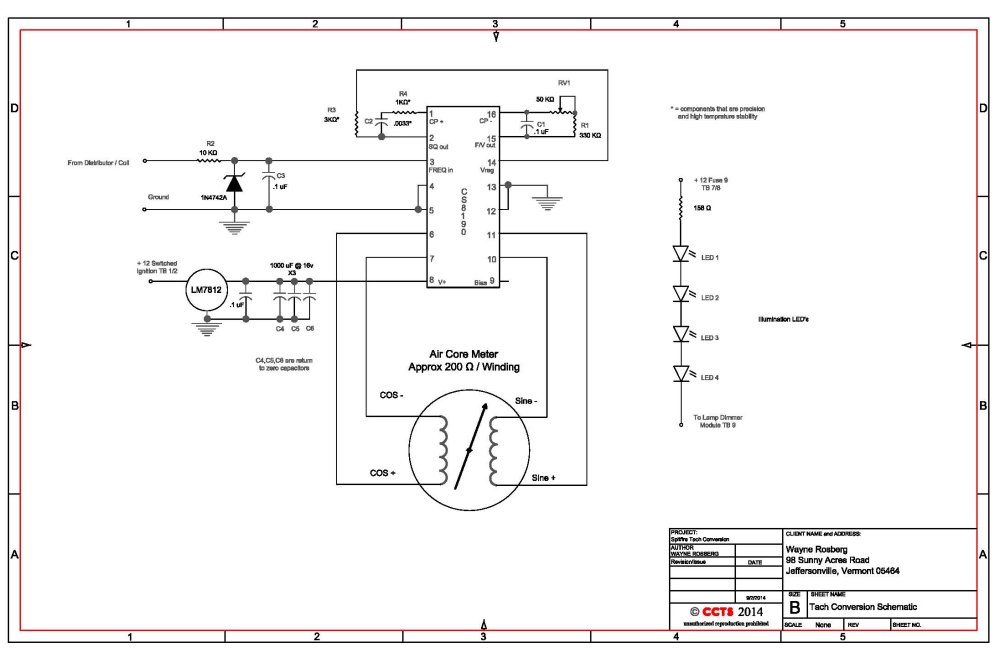
So Down To Nuts And Bolts: The driver chip chosen is a CS8190. It is a frequency to voltage converter with reference and motor driver in a dual in line package.
The package chosen is a hole through mounting so that circuit board fabrication in small quantities is made more efficient.
This is the basic circuit used: Click Here for a PDF of the CS8190 data sheet.
Click Here for a PDF of the tachometer schematic.
The electronic portion is relatively easy. Applying it to the actual mechanical components is not as straight forward. Some custom manufacturing and ability to handle very small parts
is a requirement.
The original dial pointer and the motor shaft of the new / donor meter motor are not the same size. A portion of the pointer shaft from the donor motor pointer
was cut off using a jewelers saw. The mounting part of the original pointer was drilled out to accommodate the cut off part of the donor pointer shaft, which was pressed in.
It is about a .0015 to .002
press fit, so for the size it is rather a tight fit. (This is an estimate not an actual measurement.) Once fitted, the new pointer shaft needed to be trimmed shorter to make it fit within the tachometer.
This was done with jewelers tools.
Once the motor was fitted to the faceplate and the pointer fitting sorted out, the circuit board was attached to the motor. It is important to
note that the pointer was not actually installed until the end of the mechanical construction.
The assembled unit was calibrated using a known frequency source and frequency counter with reference to NIST.... not that this application is all that critical.
Easy calibration points are 33.33 hZ = 1000 rpm, 100 hZ = 3000 Rpm and 200 hZ = 6000 RPM. (This of course for a 4 cylinder engine.) One will find that this circuit is much more accurate than the Smiths
electronic tachometers that were produced for that period in time.
My cost in materials was approximately $50 US. However, I also had in place the ability to manufacture circuit assemblies, jewelers tools,
Autocad and other aids for design and construction. Without these, it would have not made any sense financially to attempt the project... unless it ................
is just something one would like the challenge of doing.