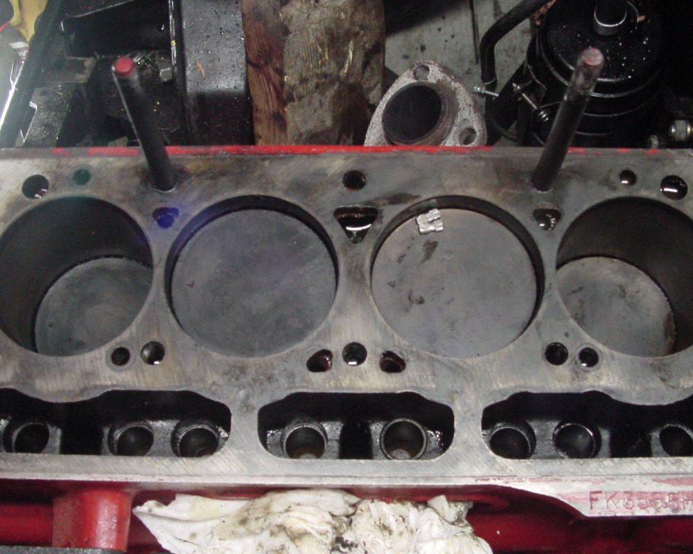
1971 Triumph Spitfire Rebuild.
Spitfire Main Page|Spitfire Electrical|SU Carb Photos|Panel Dimmer|Dash Templates|Tach Conversion|Gauge Mods|Kick Panels|Engine Fiasco|InMotion! Buttons

My Great Engine Fiasco
Otherwise known as "Fix It Until It's broken"

It was a cold winter night here on Hazard Heights. I decided not having had any abuse in at least 2 hours, I'd connect
the battery charger to the Spitfire. That went just fine.

I then decided Oh what the heck and went to start it. As a point of reference, I do not have my choke cable
installed. So the way to start this when it is cold is to reach over the engine and operate the choke with one hand and
reach through the windscreen that is not there and operate the ignition switch.

This is somewhat awkward, but usually works if you hold your mouth just right.

This time, it didn't want to start and I thought I flooded it, so I took the plugs out. Sure enough they were wet.
So I dried them off and tried again. This time it wanted to start, but didn't and I repeated the process of drying the wet plugs.

After re-installing the plugs, I tried again and it started. There was only one problem. The was a very serious bad rapping noise coming from the engine.
Click here to listen

Well after much consternation, and some "Vocabulary Enhancement", the oil pan was removed, the timing cover was removed, the valve train was inspected,
everything that I and folks at the Triumph Experience could come up with I pulled the head.

There it was sitting on top of cylinder #3 piston. It is, or should I say was an aluminum top to a spark plug.
The NGK plugs I have installed have been in the engine for about a year and a half.

The only thing we can think of is that this piece may have been floating in the spark plug well for some time and
I managed to push it in when replacing the plugs. All the plugs do have their tops on them.

Fortunately it was aluminum and did no damage. It was also stuck to the far side of the piston and was not visible through the plug hole.
Also, it being aluminum, was not attracted to the magnet that was used in each cylinder.

Of course trouble finding involved removing bearing caps etc so now the engine will require removal and through inspection
before reassembly.

Here is the culprit. By the way, the head took some special language to get it removed.


1971 Triumph Spitfire Piston Bore, Big End and Main Bearings Etc


When these photos were taken, Rods #1 and #4 were disconnected. If the pistons seem out of place
from the normal relationship, it is because they are.

There is no scoring or marking in any of the cylinder walls. What ridge there is on the top of
the cylinders appears to be carbon buildup. These photos were also taken before all debris was removed.


Cylinder #1


Cylinder #2


Cylinder #3


Cylinder #4


Cylinder bore measurements were taken for each cylinder.

Method:
A telescoping gauge and a 3 inch micrometer were used. The accuracy using this method is probably within +/- .001 inch
Measurements were taken near the bottom, the middle and the top of the bore.
In each case a measurement was taken perpendicular, and one parallel to the center line of the car. (Left to right and front to back.)
Measurements A, C and E are perpendicular. Measurements B, D and F are parallel.

Results of the measurements show that all 4 cylinders are very close to the bore specification of 2.900 inches. This is probably
the limit of my ability to measure this. The couple measurements less than the specification may be measurement error, although all measurements
were made multiple times.

Measurement Location Cylinder #1 Cylinder #2 Cylinder #3 Cylinder #4
A Bottom 2.901 2.900 2.900 2.899
B Bottom 2.900 2.900 2.900 2.901
C Middle 2.900 2.901 2.8995 2.900
D Middle 2.901 2.901 2.900 2.901
E Top 2.901 2.9025 2.9015 2.901
F Top 2.901 2.903 2.9015 2.901


Crankshaft and big end bearings:

Measurements were made of the crank journals using both a micrometer and a caliper. No measurement was made of the center main bearing.
The front and rear main bearings were not disassembled.

As the engine is still installed in the car, I find it difficult making these measurements laying under the car. I have decided that the engine must
be removed. I understand it is possible to make measurements and replace bearings etc with the engine in the car. However I
can not do this job properly this way and I currently do not have access to a lift.

The big end bearings all measured 1.875 inches, which is the specification. It was difficult to obtain multiple measurements around each journal.


In the following photo from left to right are cylinders #1 through 4 big end bearings.
They are arranged to show the worst wear spots.


The is the lower bearing shell for the middle main bearing. This one is showing a lot of copper, but no scoring
of the crank shaft.


1971 Triumph Spitfire Head And Valves


Head as it was found after removal.


Head after removing most of the carbon


Valve seats after cleaning. Note that the flash on the camera accentuates roughness in the metal.


I made measurements of valve stems, valve guides and valve spring free length. The latter is probably not very useful as the springs have one side slightly shorter than the other.
I tried to get the longest side. This was more just to see if there were any really big differences.

Method:
The valve stems were measured at three points of the traveled part of the stem. The were also measured at the same point but 90 degrees apart. So point A would be closest to the top of the stem and B would be at that same length but after turning the valve 90 degrees. Likewise C and D would be at the mid point and E and F would be
closest to the valve head. This was to get some idea if anything was out of round or worn substantially different
over the length of the valve stem. All measurements were made with a micrometer.

The valve guide diameter was not easy to measure. My smallest telescoping gauge will go down to .308, but I question the accuracy of
the measurements. I was however, by sliding the gauge through the length of the valve guide, that there were no
substantial differences noted from one end to the other. The measurements recorded were at the valve head end of the guide.

Valve Measurement Data is Here


Triumph Spitfire Cam Followers


Cam Bearings
5-31-2015,

Unlike some of the other engines this particular one does have cam bearings. The front bearing did not look all that great so
I decided to replace them. I even have the proper tool to do so, NO threaded rod.

I opened up the bearing package to have a look, unfortunately this was after removing the old bearings.

The new ones are County bearings made in India, which have been reported to have issues with the shell thickness.
We'll see. The parts source is very reputable so no worries.

6-6-2015,

Checked the thickness of the cam bearings the other day. Everything looks good so far. I won't install until the block has been cleaned.

Today checked the diameter of the cam follower bores. All look on the money at .800 inches.
Ran a quick 320 grit ball hone on each one to break out the crud. Measurements before and after the same.

Bored the oil passage to the middle main out to 5/16. Tapped and plugged the oil passage from the rear cam bearing to the head. Tapped and plugged the same oil passage
in the head. The rocker oil system will be taken from the rear oil gallery adjacent to the rear main bearing via an external line to the rear oil port on the head.

The other day I pulled the transmission and bell housing from the car separately. I now remember the bottom bolt of the transmission is not blind and
the transmission oil will leak out, so I put the bolt back in right away. I then set the transmission on the passenger floor. Today I find that the oil leaked past the finger
tight bolt and the passenger floor is now well lubricated. Well it is a bit of a mess to clean up..... but I don't think it will rust. My stupidity but not the end of the world.
Oh... there are no carpets or anything other than some oily speaker wires laid in there.

Anyway the plan is to put the engine and transmission back in as a unit rather than trying to mate the two in the car.


7-2-2015

Installed new cam bearings and the cam.

Installed new main bearings, Custom Thrust Washers and the crank shaft.


Cambridge Communications and Technical Services Inc.
98 Sunny Acres Road
Jeffersonville, Vermont 05464

©CCTS 2001 -