
1971 Triumph Spitfire Rebuild.
1971 Triumph Spitfire Rebuild.
This discussion is primarily directed at panel or dash illumination and
retrofitting LED devices to original incandescent design. We will not attempt to
cover microprocessor based or bus architecture control systems. (This is a
Triumph Spitfire.......)
Most automobiles up until about perhaps sometime in the 1990's were fitted with a simple
variable resistor, sometimes called a rheostat to control panel illumination.
This was pretty straight forward. One had a known quantity of bulbs at a certain
resistance, that together would cause a predictable amount of current
to be drawn. An incandescent bulb exhibits a relatively linear light
output over a fairly wide input voltage. So simply, the light output is about
half when the voltage is half, so the
variable resistor was all that was needed. However if one or two lamps burned
out, the adjustment range broadened and the circuit did not work well. One for
the most part
could apply Ohms Law to determine the circuit characteristics.
The fact of the matter is that this is a bit of an oversimplification. Lamp resistance changes as the filament temperature changes, but so as not to make this rocket science.... I'll go with it
A LED on the other hand, although exhibiting a relatively linear output does
so in a very narrow range. First unlike a bulb, which is a resistive
device, the diode needs to overcome the forward
threshold and start to conduct before it begins to function. So in a sense the
LED goes from an off to an on state at some point. It is a very dim on condition
but on nevertheless.
The graph below depicts the relatively linear incandescent curve as opposed
to the fast rising current curve of the LED.

Another issued faced with retrofitting LED technology to older circuits is
the usual necessity of having to keep some of the original incandescent
lighting. One of the immediate
problems is the brightness of the bulb versus the LED.
If we consider a typical replacement bulb for the Spitfire it might be a 1487
or a 1815 bulb, depending if it is screw or bayonet base. The original bulbs
were a 2 watt version, these are a 2.8 watt version.
In any event, the bulbs light output is almost spherical, that is it glows
equally in all directions, except for the dead spot at the base. So
the rating given to them
is MSCP, or Mean Spherical Candle Power, or the light in all directions. In this
case the MSCP for these bulbs is 1.4
LED's are usually rated in mcd or millicandella.
To actually compare, we need a unit of measurement common to both. That would be the Lumen or the actual light output.
To convert MCD, milli candela to candela divide by 1000. So my 25000
mcd LED is really 25 candela, but at 15 degrees
beam width. ( By the way this is a really, really bright LED.) If you multiply
the candela by the degree beam width ( steradians), you can get the lumens
but first you need the steradians.
(Note: If doing this calculation in Excel, be sure to convert the COS function from radians to degrees.)
In this case 15 degrees is .2137 steradians X 25 Candela = 5.34
Lumen. To obtain the spherical value to compare to
the light bulb, divide 5.34 lumen by 4 PI or 12.56 = .425 MSCP. This is not
quite the 1.4 MSCP rating of the bulb.
There is however still one other problem, if you call it that. The LED, even
if you do the math and make the comparison is still in this case a 15
degree device. We can not change that. But this does show that even though the
LED uses less power and seems brighter it really is simply
the lens in the LED that makes it appear brighter.
The bulb at full brightness is 2.8 watts of consumption. The LED is .28 watts
of consumption at the same voltage using a single LED and current limiting
resistor. So that's approximately 1/10th the power for 1/3 the equivalent
lumens. But a lot of the power expended in the bulb is heat. It is
estimated
that incandescent bulbs 5 watts and under are around .5 to .7 % luminous
efficiency, while an LED can be 10 to 22 %. It is this writers belief
that these numbers may be skewed by the move to ban incandescent bulbs for
general lighting.
Back to the problem at hand.
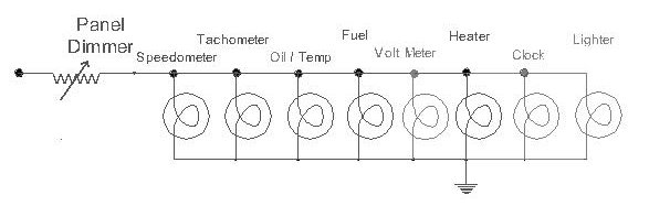
This is a typical panel dimmer circuit for the Spitfire. Some components are optional..
If all bulbs are the original 2 watt style, the total current would be
approximately 1.3 amps. Using that, the calculated resistance of the lamps would
be
about 9 ohms. So using ohms law calculations, if the panel dimmer were set
to maximum resistance, around 24 ohms, the voltage drop would be
9.12 volts across the resistor and 3.48 volts across the bulbs.
If one changes these bulbs to the newer 2.8 watt versions to try to brighten
the gauges, the total power increases from 16 to 22.4 watts. Or 1.8
amps total light current. When the dimmer is in the maximum dim position,
24 ohms, the calculated current only increases slightly and the voltage drop
across
the resistor is now 9.24 volts or 3.55 watts dissipation.
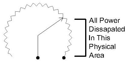
However the dimmer is usually not in the lowest position. It is typically all
the way up, negating its purpose, or it is about 75%
the way up. In this case the resistor is dissipating about 6 watts of power, but
it is doing it in 25 % of the controls physical structure.
So if we are looking at backlighting a gauge that requires a diffuse light, a
single LED
is typically not the answer.
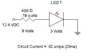
This is the typical single LED with dropping resistor circuit. The LED's I am
using have a forward voltage drop
of very close to 3 volts. Other LED's will vary . I am also using the
specification of 20 milliamperes. Some LED's are specified
at 30 ma. The current specified for the device can vary. I've run LED's up
to 200 ma in test. At some point they can actually change color,
and even dim as current increases. This is slightly before they become an FED, a
Flame Emitting Diode.
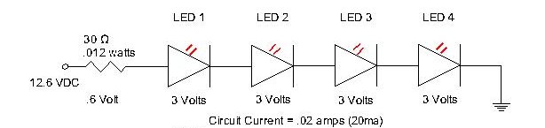
Another variation, and one that I'll be using in the speedometer and have
currently designed into the tachometer conversion
is 4 LEDs in series. The advantage is that only .012 watts of power need to be
compensated for as the LED's drop most of
the 12 volts. This also has an advantage in a larger gauge as they are
positioned at the 12, 3, 6, and 9 o clock positions and facing to the front
of the gauge. This is opposed to the single point light source relying on diffusion
of a plastic piece and reflection from the inside of the gauge.
(This is an internal gauge modification.) The LED locations are at
the red circles on the perimeter of the circuit board. The circle in the upper
part of the board
is the cut out for the stock incandescent bulb if desired.
Tachometer Circuit Board
Showing LED Placement

In this case the LED directivity can be used to its advantage. The
LED faces forward and is reflected off the painted gauge housing and the rear of
the
tachometer face to provide a diffuse lighting pattern.
This circuit will dim quite nicely and linearly, however it does it all within
about a 1 1/2 volt range. The LEDs are off at 9.2 volts, trigger on at 10
volts,
and achieve full brightness at 12.6 volts. Not all LED's have this same
characteristic which complicates the issue.
The Spitfire panel dimmer, if fitted, is a variable resistor with a range of
about 1 to 24 ohms. If we use E=I*R
we can see that the voltage drop across this at 24 ohms is .48 volts. However as
the LED is not a resistive device,
all we are doing at this point is varying the amount of heat dissipated by the
resistor. This is because at this point
the LED's are still conducting at a fairly constant 20 milliamperes, and we have
not got down to the theoretical
12 volts where we can affect the current.
We can add light bulbs to increase the current thus the voltage drop across
the dimmer, however due to the very different
characteristics of the devices, they do not dim equally. And, if we are going to
add bulbs to try to solve the problem,
why bother with LEDs at all?
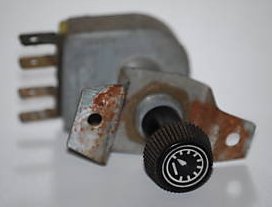
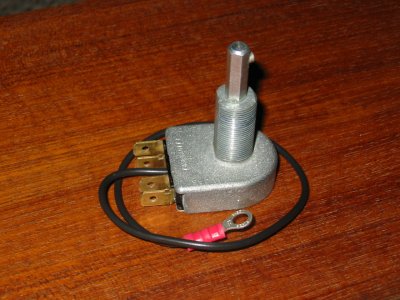
A typical Spitfire panel dimmer.
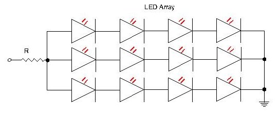
The following is a schematic representation of a typical LED
array used in replacement bulb technology. The
number of LED gangs may be more or less. Many, but not all of these on the
market use a single current limiting resistor
as depicted in the schematic. It all depends on the chip style LED that is used
and the mechanical configuration.
The most practical way to reliably dim both LED's and / or
incandescent bulbs is by varying the duty cycle that the devices are on versus
off.
This is also known a Pulse Width Control. The following graph illustrates the
concept. At 50 % duty cycle the LED is on the same amount of time it is off
resulting in about half relative brightness. Similarly, at 90% duty cycle,
or on 90% of the time the LED is at nearly full brightness and conversly at
10% duty cycle the LED is off 90% of the time and therefore very dim. This
happens at a fairly high frequency. In my circuit it is approximately 250 hZ

I've built a
solid
state dimmer module. It uses a simple timer chip as a pulse width modulator
to vary the time the LEDs and or bulbs are on as opposed to the time they are
off. It does not matter if it is LED's
or incandescent bulbs or a combination.
This does not effect the life of the bulb or LED.
This does
require rewiring the circuit as the bulbs are switched to negative ground. This means that you supply 12 volts to one side of
all the
illumination bulbs and / or LED's and the return to ground or car chassis goes
through the module. I've built it both ways, ie the type
that requires no wiring modifications. For my purposes, this design works
best, but does require the wiring modification that probably very few
would want to tackle. One of the reasons I'm using this configuration is to
minimize electrical noise as the car will contain some communications equipment.
As I'm rewiring the entire car anyway, this is no big
deal. This does require changing some of the illumination sockets to
ones that do not electrically connect to the gauge housing. In the case of the
speedo, one needs to provide another way of grounding as the gauge regulator
gets its negative side as part of the housing through the original lamp socket
ground. The regulator has been converted to solid state as well. However
in my
application it is not needed as the only gauge needing regulation is the fuel
gauge and that is built into it. And as I plan an internal lighting circuit
board, this is probably a non issue.
I have found that stock lamp holder for the ignition switch
illumination is
perfect for this. Victoria British sells a version, however I do not know
if it is case isolated or not. Their
part # is 14-971, but again, not sure if this is isolated. I had enough
sockets between everything to do what I need so I've not ordered any.
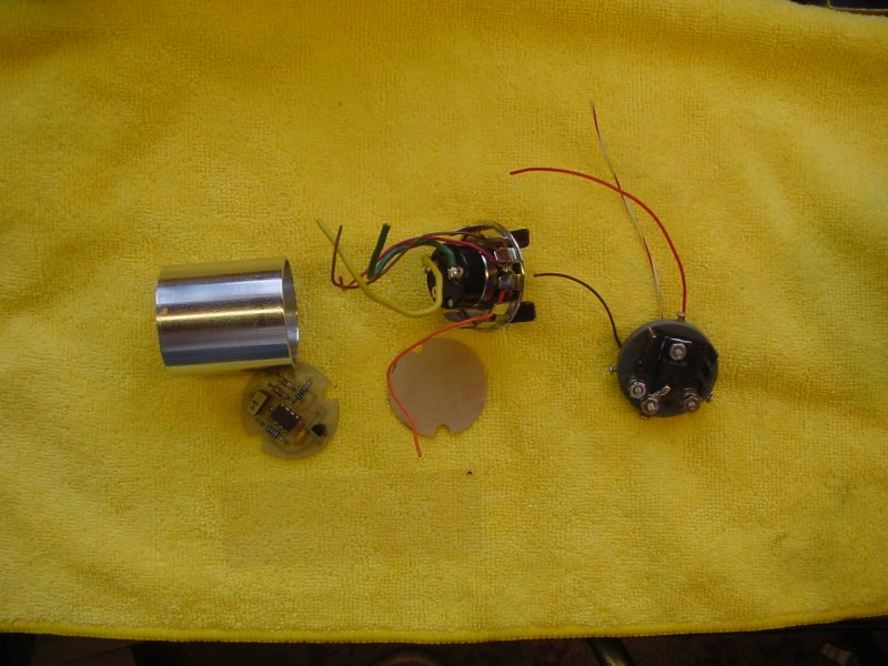
On the back of the module are the connections and a power transistor on a
small heat sink. This generates no measurable heat even with over 4 amps
of current.
The switching transistor
is good for 12 amps but we rate it at 4 maximum. If it fails it should
fail with bulbs on full brightness.
The switch on the pot is to control courtesy lighting manually, something Spitfires never had.
It looks like this:
This lamp is actually at half brightness. LEDs work the same on this as the lamp does.
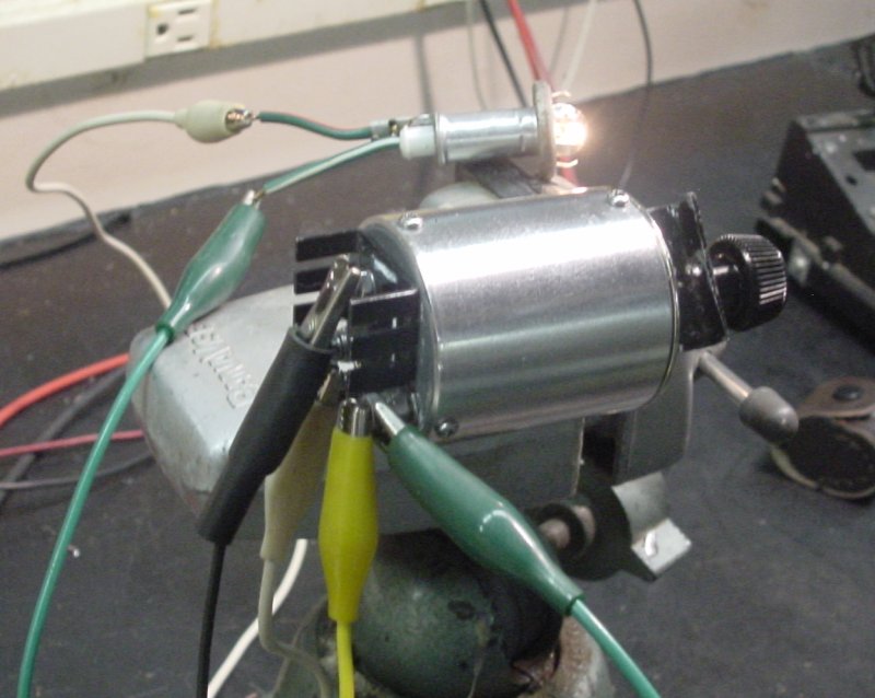
Plug and Play Dimmer Unit
A solid state replacement for the Spitfire Panel Dimmer can be
found at the following web site that advertises an Over Drive
Controller.
Look for the link for Dashlight Dimmer Retrofit. I have no affiliation nor have
any experience with this product or the company producing it.
I offer this for informational purposes only. I have e mailed the owner and have
been given permission to post this.
This looks like a very nice solution at a very reasonable price.
http://od_cntl.webring.com/Overdrive_Controller.shtml
Or e mail: od_cntl@hotmail.com
Ohms Law chart for your reference.

When you've let the smoke out....., Get This

Cambridge Communications and Technical Services
Inc.
98 Sunny Acres Road
Jeffersonville, Vermont 05464