Planning the rewiring. After considering replacing the wiring harness with an after market one, or
attempting to find a decent used one, the decision to re-design and construct a custom electrical system was made.
I am not suggesting that this generally be done. I must repaeat, this is a total wiring replacement. This is not at all advisable for the electrically faint at heart!!!
As this is to be a driver and not a restoration, electrical originality
is not the primary concern as long as the outward appearance of the car is for the most part retained.
There were originally
only three fuses in the car and all the heavy currents ran through the
switches
in the dash. I think the only relays were the starter and horn
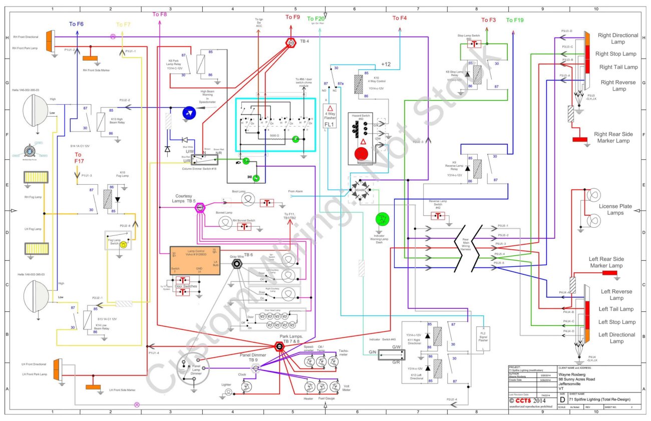
relays. The next diagram is of the new lighting circuit.
This is the final revision. Posted July 4, 2014 .
Note that these diagrams may not be complete.
Anything used from these diagrams you do so at your own risk.
Questions / comments are welcome by using the e mail link at the bottom of the page.
Main system wiring diagram. This is the final iteration. This was posted
July 4, 2014.

To combat the usual and continual ground problems with the car, a full ground system was installed. Additionally
each bulb in the car, including all rear lamps have an independent ground wire to a common ground point, rather than relying on plated pot metal.

Anyone interested in these diagrams cancontact me
by using the e mail link at the very end of this page.
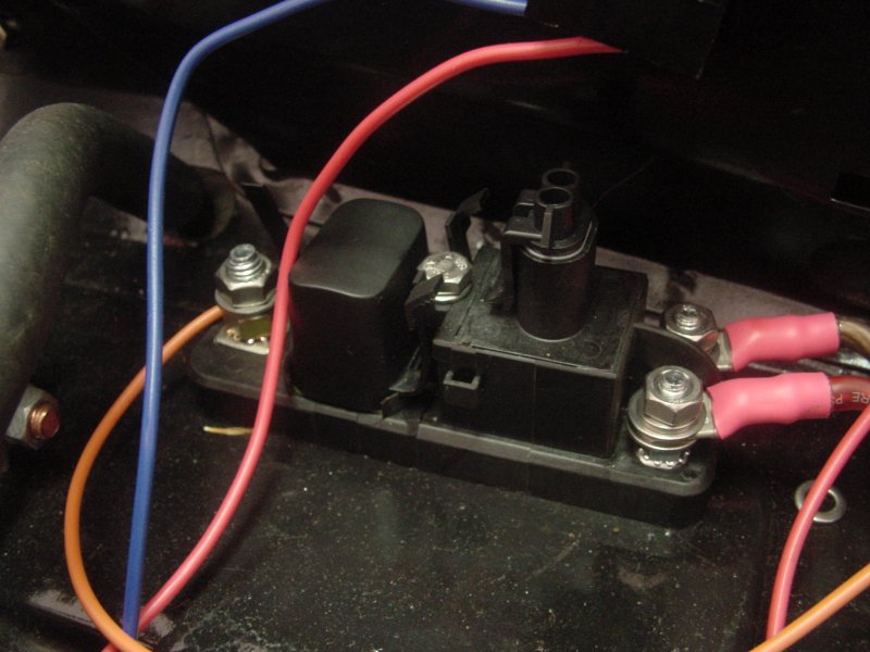
The new fuse block mounted near the clutch master cylinder.
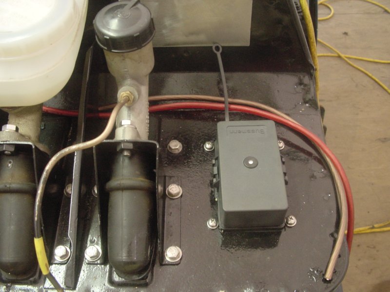
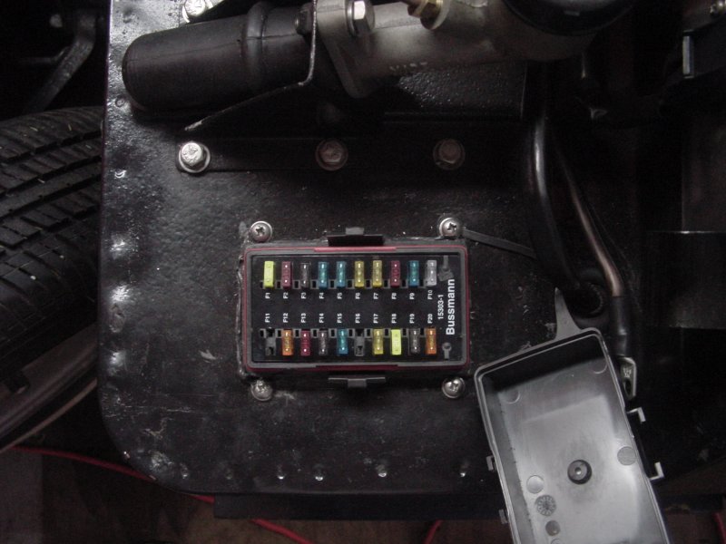
Main Relay: The battery feeds the left terminal in the photo to a pair of fuses. One fuse is straight through to the always hot side of the fuse block
(red wire). The other fuse feeds an internal relay that feeds the ignition switched side of the fuse block (brown wire).
The Metripak connector on top is the connection to the relay coil. It mounts by a single 1/4 inch bolt in the center.
The fuse block PDF spec sheet is here. The model used here is Cooper / Bussman 15303-1-2-3
The power distribution relay PDF spec sheet is here. This is a Cooper / Bussman 37702-1AN022
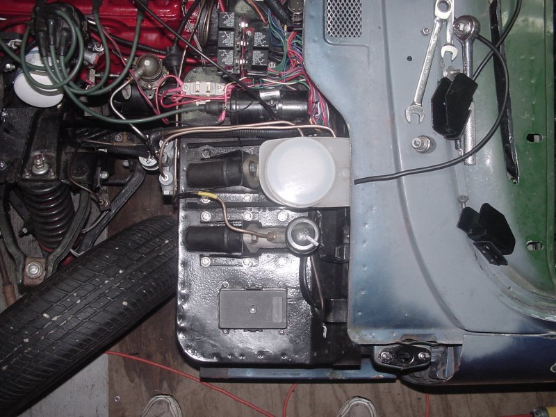
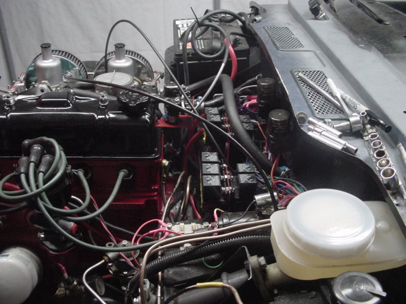
Chronologically, this photo should go further down the page. The two relay bays are on the bulk head.
This is before lacing the harness.
The flasher units on the upper bulk head are solid state. I find the down side is that if you have a bulb out
they will still flash at the same rate. They will however support both incandescent or LED lighting or a combination.
Various Delphi Metripack 150 and 280 series connectors are used throughout. This is one of the 10 position 150 series
used. This is one end of the two new harnesses to the rear. The harness to the front lighting uses 280 series 5 position
with #10 wire feeding the main lighting circuits, #12 feeding the fog lights.

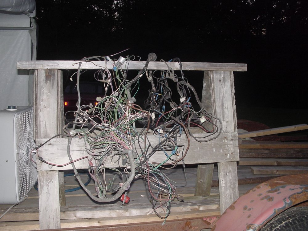
Pulled the "too far gone" wiring harness out of the 76 body. If
I could sell all the wire nuts, weird splices and used electrical tape.............
This one is extremely messed up. There are a lot of butt splices
and wire nuts. I've saved the original 1971 harness which is in pretty good
shape.
Eventually the 1976 harness was dismantled in sections as much as possible. All the
fittings such as light sockets, etc have been saved for possible use
on the new harness. I am not going to use the original 1971 harness, but as it
is in pretty good shape, I'd like to keep it as intact as possible. Someone might need it.
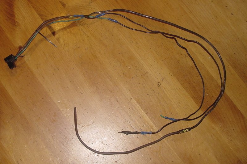
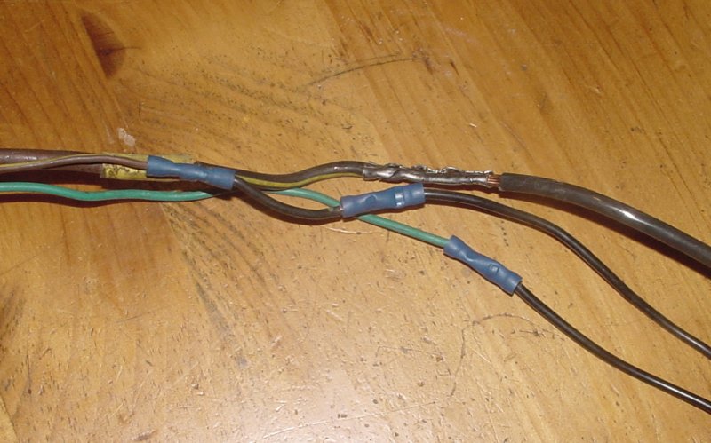
This is part of the wiring harness from the photo above
This is the wiring to the alternator plug. I was
wondering what all the lumps of black tape were hiding.
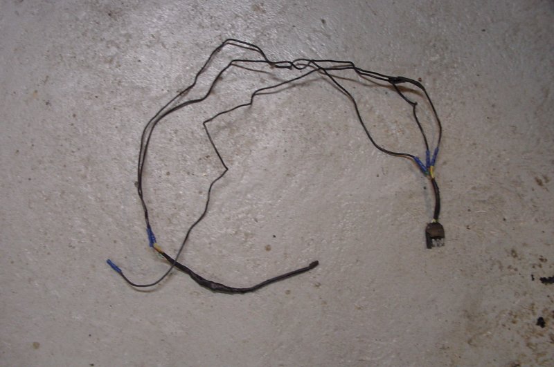
Then of course one must have option 001, the customized trailer wiring. Well it is a trailer connector that was extracted from
the snarl-o-wires. But if you look closely, that is a male connector. Last I knew, the car end should be female and the trailer end should be male.
Didn't bother to look at what was under all that tape.
A trailer option was not included in the new wiring harness.
10-1-2013:
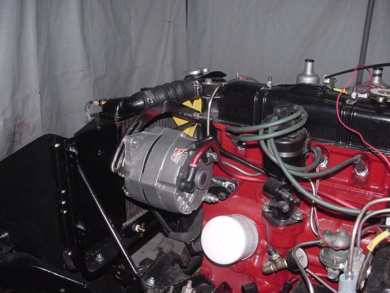
The debate is over as to when to replace the Lucas alternator.
I was putting together the wiring harness and decided
now was the time to install the Delco 63 amp in place of the 30 amp Lucas.
I used a Mr. Gasket #9851 universal bracket for the top
adjuster. Had to cut the end off and drill a 5/16 hole in it. I used a 3/8
SS nut as a spacer and replaced the original
bolt with a longer one, I think it went from 2.5 to 3 inches long.
The bottom bolt was originally 5 inches long. A 4.25 inch bolt would seem
to be perfect however the local
hardware store only had bolts up to 4 inches, so I improvised for now and put a
spacer in back. I'll find the correct length bolt.
The lower alternator mount is also 3/8 not 5/16 as the original. I used a
piece of drawn aluminum tubing
3/8 (.375) OD and .305 ID. 5/16 is .3125, so we put the tube in a lathe
and used a 5/16 inch reamer
in the end stock of the lathe to get the correct size. You need 2 inches
of this bushing. The aluminum
tube is 6061-T6 or hard aluminum (aircraft aluminum) so it machines well.
The original fan belt was too short.
I ended up using a #15460 which is 1.5 inches longer than the original.
I used #6 wire for the main feed. The alternator feed back and charge lamp wires
are run through wire loom. For this wiring I used the
shell of a new plug and inserted new connector pins and cable so that there
would not be any splices.
In this photo the engine is actually running at an 800 RPM
idle. The fan appears still due to the flash.
Cleaning out the basement and trying to organize parts.
Today
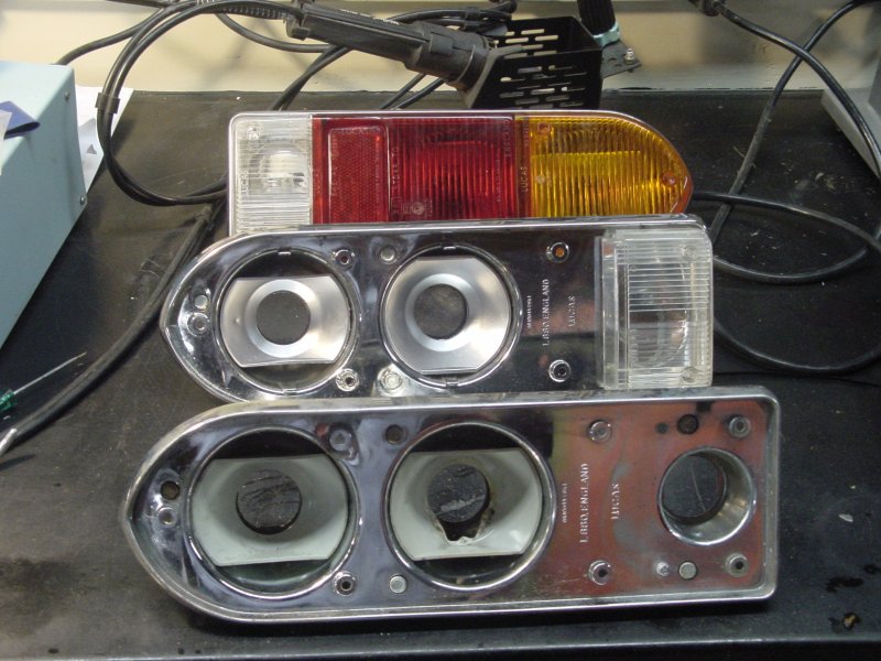
11-23-2013, did some more organizing and worked on some of the lighting.
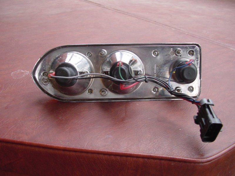
Made a set of good tail light assemblies out of the 2 sets and various parts of
sets. Had a new reverse lamp lens for one of them. Lots of
cleaning...
The front is one of the typical lamp assemblies with melted parts etc....
one tail light assembly showing restored interior and the one in the back
is a finished one except for the new gaskets that I'll have to get. Another
modification is individual grounds for each bulb socket
rather than relying on the problematic grounding originally used.
Had a request / question about grounding on the rear lamps. I realized I never posted any photos of the
boot side of the lamp assemblies. There is also a ground to the assembly. The grounds on the other side of
the Metripak 150 connector go to a common boot ground that is fed by #6 wire. The ground system is shown earlier on this page.
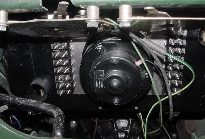
Wire Junctions
I continued to run into the need for junctions, almost all under the dash.
I fabricated a couple terminal blocks with studs rather than
screws and made SS brackets mounted
either side of the heater fan motor. This is the
diagram. Red are the brackets, the green is the
heater motor housing. Each holds a six position barrier strip, #8 screws.
I removed the original screws and inserted
screws from the rear of the barrier strips making them stud mount that is better
suited to ganging multiple wires.
The back side of the terminal blocks were filled in with black silicone.
Each mounting bracket got a couple of big dabs of silicone
and let sit to almost dry, then installed.
A PDF of the terminal board template is here.
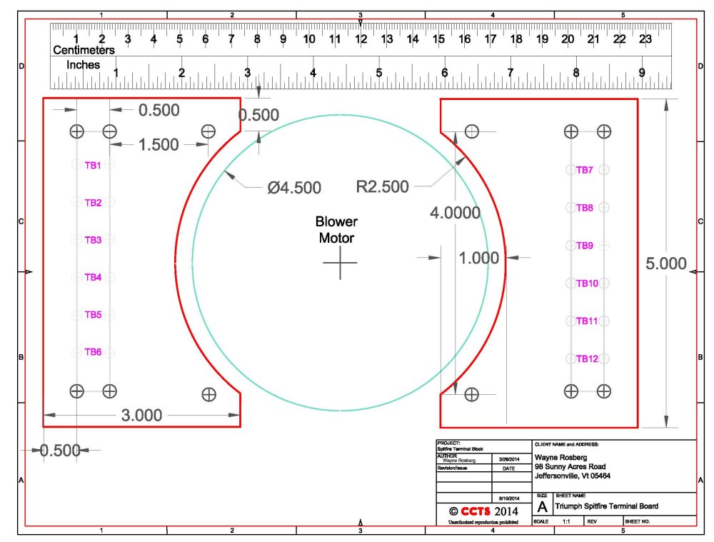
This is what it looks like.
A legitimate question and an important one came up from an observer. With the wiring terminal blocks mounted on the heater box,
how does one remove the heater if (when) it fails. The wiring all comes in from above. One should be able to unmount the terminal blocks
and remove the heater assembly down and out. Of course this is easy for me to simply say, never having actually done it.
Windshield Wiper Stuff
Finalized the wiper circuit on 4-1-2014.
The design keeps the wiper control in basically the same position on the dash, adds the intermittent wiper feature, and provides
a control for a standard washer motor /reservoir rather than the push pump on the original.
April 2, 2014, amongst other non-Spitfire related treats, made the bracket and mostly wired the control and relays for the wiper circuit.
Routed cabling for the switch and motor. Wired washer relay, connected to terminal block.
The following is the schematic and some notes. For higher resolution schematic and more notes,
please e mail me via the link at the bottom of the page..
The table of the wiper motor connections / plug connections are looking at the end of the plug on the cable to the wiper motor.
The SS module and the two relays mount on a 5 inch long x 1.5 inch wide piece of aluminum stock that is mounted to the right
of the battery box in the passenger foot well. This is essentially under the wiper motor, behind the glove compartment.
Two # 10 ss screws from the bulkhead into the passenger compartment hold the bracket in place.
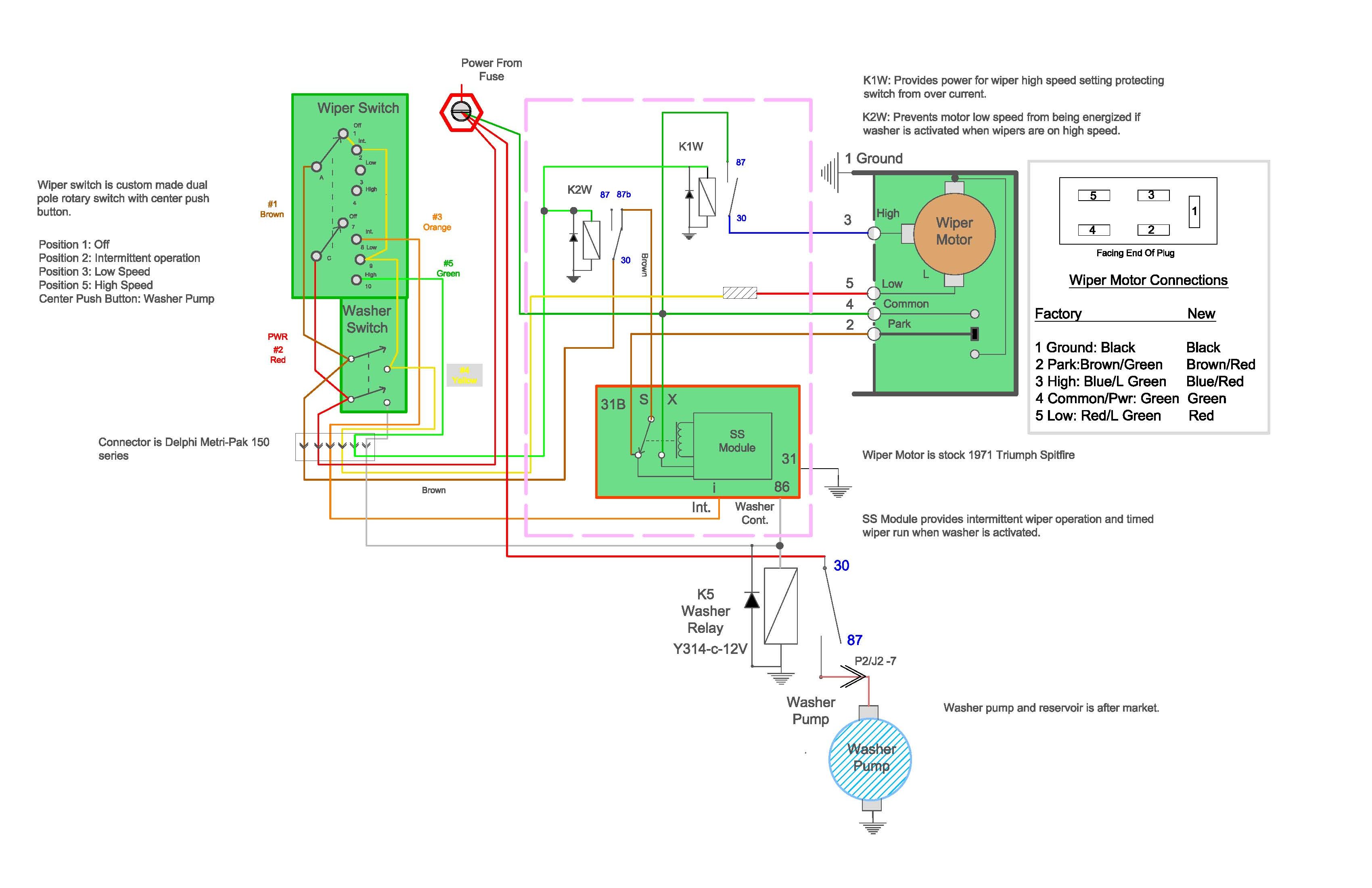
The switch combination is a custom build. It could be simpler if one wanted a separate washer button. There are
single pole washer switches commercially available that have a push function for a washer, however I could not find any
two pole units with four positions to accommodate the intermittent function. So here at Rockbottom Labs, we built one.
First we acquired a few 2 pole 4 position rotary switches. Only one is required, but this was a custom. Need one to break.
The switch was disassembled. After the ball bearings and springs were retrieved from across the shop, a 1/8 hole was drilled through the switch shaft
and the base. After a couple tries and some vocabulary "enhancement", a 1/8 shaft was passed through the switch components.
A piece of one inch ID aluminum square tube was milled out slightly so the switch would fit inside. A momentary switch was attached
to the back of the unit so the shaft would press against the switch. The standard Spitfire wiper control knob was drilled
to accommodate a small button. This button is tapered so it does not push put of the knob. The connections are via a
Delphi Metripack 150 series connector.
It looks like this: Mounting details to follow later.
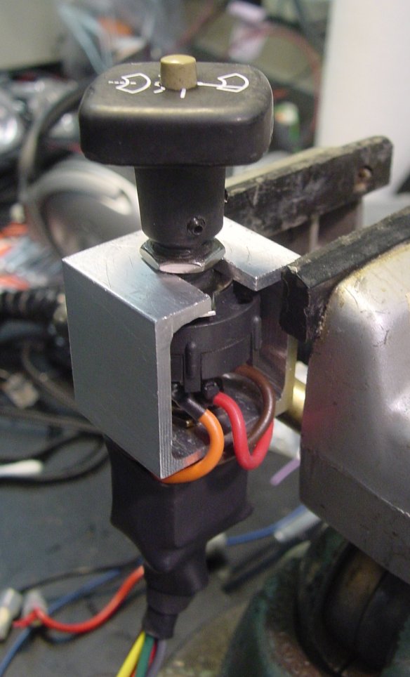
Headlight Switch
Was never happy with the original headlight circuit. I think it is a very poor, if not potentially hazardous design.
All the current for all the lights on the car ran through the panel switches. This coupled with the poor fusing technique
and lack of proper fusing was a potential recipe for disaster.
A 30 amp fuse feeding 10 amp wire scares me. I also wanted to incorporate things like daytime running lights and running light selection.
I wanted the head lamps to turn off with the ignition, and all lights to extinguish in the start position. Additionally I wanted the usual
warning if the parking lights were left on, and the key was in the ignition with the ignition off, or the lights were left on
and the door was opened. I also wanted to get rid of the annoying (insert more appropriate words here if you desire) buzzer warning
and replace it with something more palatable. A fog light switch also was to be added, so space / size versus functionality was a consideration.
Several options were considered and I finally went back to Rockbottom Labs for a new design.
As high and low beams as well as parking lamps are now relay controlled, switch current handling capability is not so much a factor.
I used an off the shelf four gang three position rotary switch. To select daytime running light options, a pair of alternate action
small push button switches are used, one for head lamps and one for marker / parking lamps.(We live near Canada which has
different requirements than the US.) I probably really didn't need to do this. However I could, so I did.
This is the wiring diagram. The brown wire with no label goes to the acc position on the ignition switch.

It looks like this before mounting on an aluminum plate. The switch shaft will be trimmed to the appropriate length later.
As of 4-6-2014 the following electrical items have been wired and are functioning:
- Directional Indicators
- Four Way Flashers
- Reverse Lamp Circuit
- Heater Fan
- Horn
- Ignition switch circuits
- Windshield Washer / Wiper
- Cooling Fan
4-8-2014; Assembled headlight switch components on metal bracket and wired. Most of the headlight wiring is complete.
4-9-2014; Found headlight ground cables and connected regular incandescent headlights to wire harness to test. All OK.
Still need to connect wire for the main beam flash function.
Sorted out some of the solid state module placement and bench wired and tested door chime / seat belt warning module.
Made up cable to connect drivers door switches.
4-10-2014: Installed drivers door switches and wired "key in" alarm and seat belt alarm module. (The "dinger" or chime
or as I call it the necessary annoying device.) I've put it on its own fuse that can be easily pulled to mute it.
The door switch with two tabs, or isolated from ground seems hard to get, or it randomly arrives when ordering the single tab switch. Substitutes at Rimmer Brothers and others are listed
however they appear to be a grounding type switch as is used for lighting. I guess if you have one of these hold on to it.
I'm sure there are many others that will work electrically, but not be the same mechanically.
Mounted the fog lamps and wired what had not already been wired. Basically from the control relay to the lamps.
Installed the wiring to the fog lamp switch and tested. One minor quirk with the fog light indicator.
Checked system voltage with fog lamps, headlights, parking lights, heater fan on high and 4 ways flashing. 14.5 volts at idle, 14.7 volts at 3000 rpm.
4-11-2014; Got started on one thing and ended up on another. Installed the connector under the dash to connect the rear harness to.
The rear wiring harness was
installed. The rear lighting got set in place. (All the lighting is installed temporarily for testing.)
As of 4-11-2014
- Rear Parking Lamps
- Brake Lights
- Reverse Lights
- Rear Directional / 4 Way flashers
- License Plate Lamps
are functional.
Did temporary
install of power antenna in the left rear fender. There was already a hole there for an antenna.
Fits quite nicely actually and is very tall when extended. Not one of those compact antennas that extends a whopping 18 inches or so.
I was impressed with the quality. The motor appears to be a Denso motor, Japanese. It looks identical to the ones in my Volvo 850's.
Somewhere I have a right angle mounting bracket from a Volvo 850 which will make mounting the motor unit easy.
The mast housing is stainless steel as is the mast. The mast extends 31 inches or so. The unit features a separate motor and mast head
coupled together with a beefy flexible tube. The motor unit sits nicely over the left rear wheel well. You can buy this at Crutchfield
a little less money.
Retro Sounds PA-02 Antenna

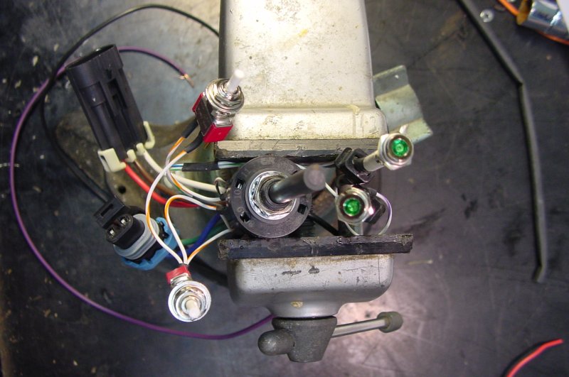
4-13-2014: Wired ground cable to drivers side bulkhead. This ground point serves the drivers side instrument area and continues on to the boot.
In the process re-worked the temporary ground points, mounted the relay banks.
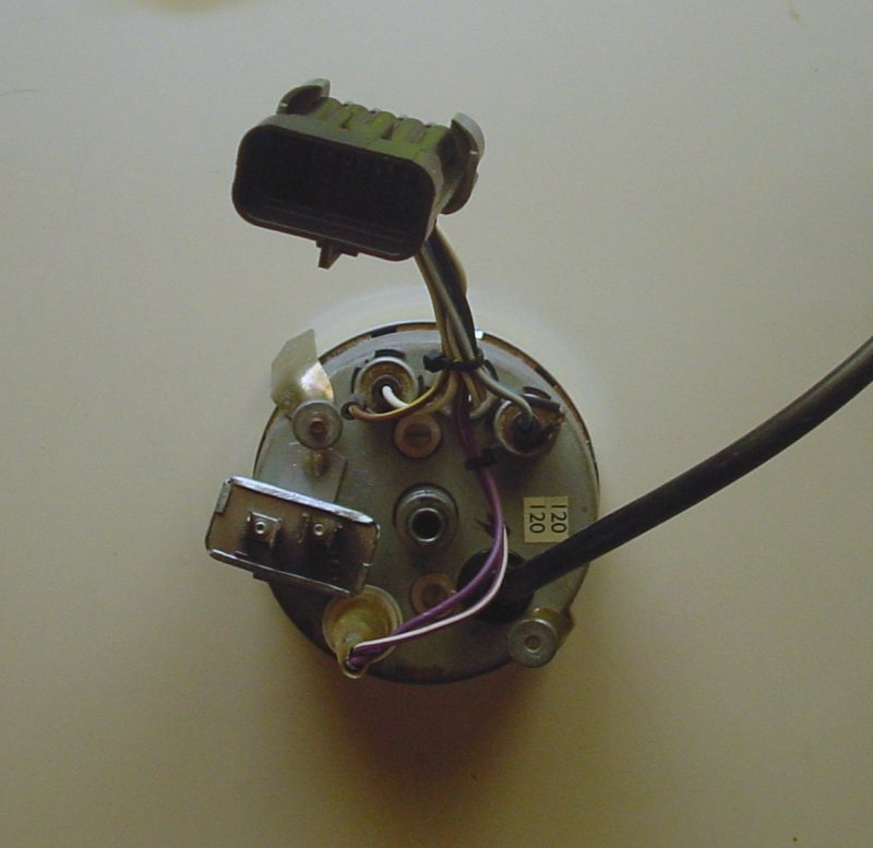
Wired the speedometer connector and most of its mate behind the dash. Used a Delphi Metripak 150 ten position connector. One connector
does the whole speedometer. In the following photo the connector does not show well. The voltage regulator was converted to solid state.
However it will be removed as it is now not needed. Only the fuel gauge now needs 10 volts regulated and I've built that into the gauge.
6-24-2014:
Been planning to have an overhead courtesy lamp but have just gotten to work on it. A wire pair was run from the passenger kick panel and through the
windscreen frame. A 5/16 hole to accommodate a grommet was drilled over the drivers position and behind the sun visor on the underside of the frame
and the wire snaked through that. A counter bore was used to minimize any burr on the inside of the frame. I ended up using #20 wire as the lamp assembly only draws .060 amperes.
The issue here is the circuit fuse size and the wire size.
As this is a LED fixture there is no need of large wire, however after running the wire, it appears that there may be sharp edges inside the windscreen frame
and if the supply side of the circuit is shorted, I wanted the fuse to blow. I had originally fused the courtesy lamp circuit with a 10 amp fuse. Doing
a test with a piece of the same wire and length and 10 amp fuse on the battery terminals proved a 10 amp would blow after several tries and several seconds, but the wire would get warm.
A 7.5 amp fuse blew instantly. As the entire circuit consumes about 2 amps absolute maximum, I changed the fuse size to 5 amps.
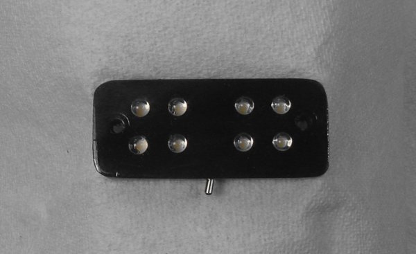
This is a drawing of the lamp assembly I designed to fit the space. I had looked at alternatives, such as LED strip lighting, however
nothing seemed to fit the car physically and aesthetically. I did not want some gaudy appliance dangling and distracting. This fixture has 8
high intensity 5 mm LED and is 1 by 2.5 inches by 3/8 of an inch thick. I've built the prototype out of wood. I may make a final version out of
aluminum.
There is a sub miniature switch that selects on with door, off and manual on.

Decided to just pot the rear with black silicone rubber.
8-26-2014:
Finally laid in the second rear harness. The primary harness is for the rear lighting. The second harness deals with things
like fuel gauge, power antenna, boot lighting, alarm stuff, ejector seat and smoke screen and depth charge controls, etc etc.
Also ran a pair of cables for rear speakers. There is a pair in enclosures that came with the car that just sit on the rear deck.
I think I'll just use them to begin with along with the ones that have been built into the kick panels.
9-1-2014: Pulled center dash panel. Added a couple dropping resistors to tame the brilliance of the headlamp switch indicators.
9-7-2014: Started connecting secondary rear wiring harness. Connected fuel gauge circuit first. Gauge
did not register. Check sender and circuits. All OK. Interestingly, the 6 gallons I had put in the tank mysteriously disappeared. Why
it appears I've been ripped off. Imagine that! Someone would actually steal gasoline. Hard to believe........
Wired accessory power to the boot. Tested power antenna.
10-28-2014: Haven't done much in a month. Tonight installed the right bonnet switch. Have been slowly working on
a couple custom engine bay lights that will mount on the underside of the bonnet. Ran the wiring through the left bonnet support tube.
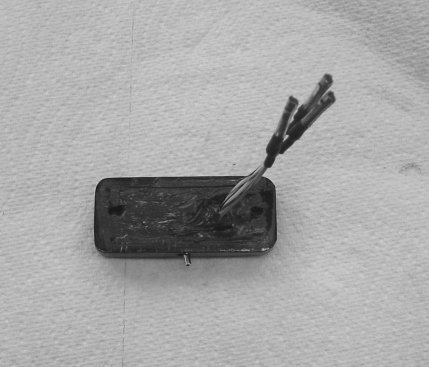
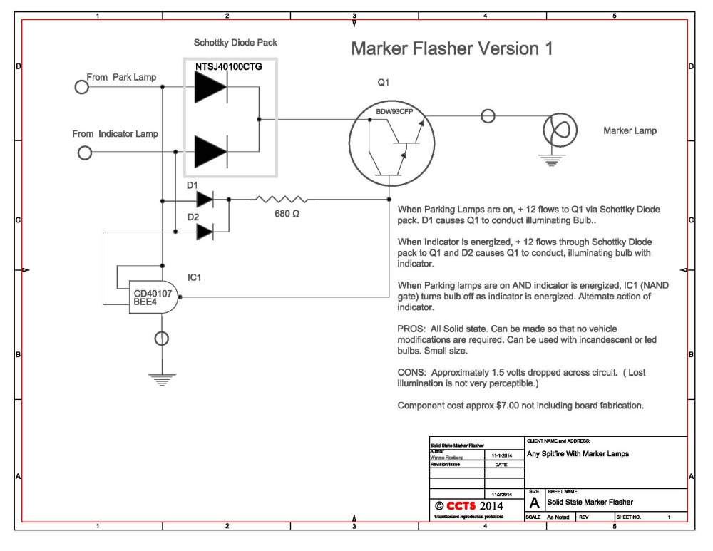
Dug out the design to make the front marker lights function as indicators as well as markers. I suppose the same could be done for the rear. I never
implemented this in the rewire of the car. This would require no modification to stock wiring other than inserting into existing bullet connectors.
I've proto typed it and built it on the bench but not a working model in the car. Might build a couple this winter
when I put my circuit board equipment back together.
This is the simplified schematic. It is all solid state and can be made very small in size. It simply diode passes the indicators to the marker bulb.
If the parking lights are on the circuit simply turns off the marker when the indicator is on. The marker will flash alternately
with the indicator when the parking lights are on and in sync with the indicator when the parking lights are off. The circuit does drop about 1.5 volts.
The change in brightness of the incandescent bulb is barely perceptible. One could overcome this by using an LED replacement bulb.
A full size PDF of the circuit is here.
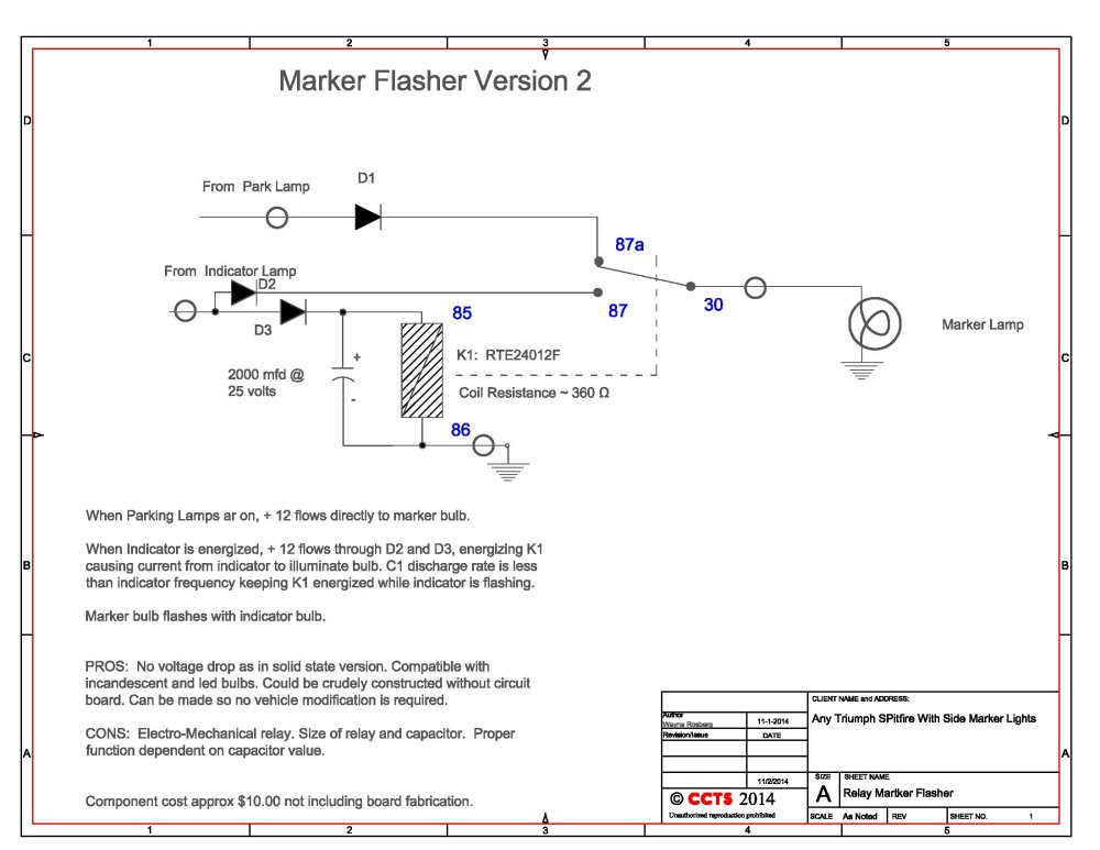
11-2-2014:
This is another way of constructing a marker flasher circuit using an ordinary relay. This particular relay is one that I happened to have several of.
It is a circuit board mount, so it may not appeal to everyone. One could substitute a standard Bosch type plug in relay or equivalent.
These typically would have ~ 90 - 100 Ω coil resistance. The capacitor would need to be in the range of 6000 µf. The relay and capacitor could
be socket mounted. The diodes could be axial lead 10 amp 100 volt such as an NTE5812HC or similar, connected to the socket via solder or push on
connectors and to the harness via bullet connectors, or by other means so long as good wiring practices are adhered to.
A full size PDF of the circuit is here.
11-23-2014:
Wired the radio and speakers in today. Connected the antenna, tested reception. Radio controls power antenna just fine. Mounted the kick panel with speakers loosly
and put the stand alone speakers on the rear deck. Sounds OK, not spectacular, but I'm used to a great sound systems in the Volvo's. This is a small convertable.
I figure if I can hear it at all while driving that will be fine. If it sounds good while the car is stopped, that is fine. I'm not going crazy with
the giga-watt amp and subwoofer in the back. You know, the one that vibrates rear view mirrors in a 9 block radius. Besides, who else wants to listen to something other than rap?


Last Updated 4-12-2015
Cambridge Communications and Technical Services
Inc.
98 Sunny Acres Road
Jeffersonville, Vermont 05464