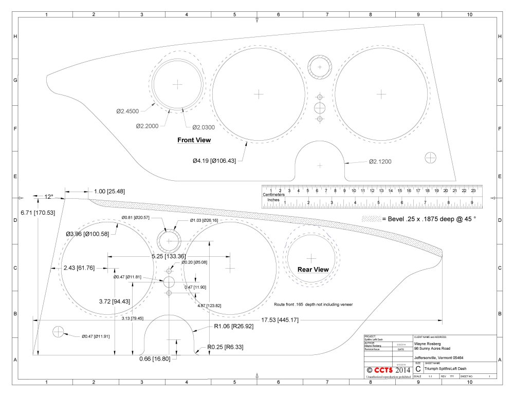
Mounting points and cut outs for wiper switch and lamp dimmer (if applicable) are not shown. Also the position for the choke cable (if applicable) has not been 100% verified.
This should probably be sorted when the panels are fit together in the car, along with the mounting studs that I forgot to put in.
The
overall dimensions and the speedometer and tachometer locations are within a few thousandths of both wooden factory panels.
Click Here for a PDF of the left dash.
UPDATE: The opening to the left of the speedometer, I believe for a GT6 air vent, appears to be located quite differently
between 1971 and 1976. One needs to verify exact location before using.
Contact me if you want full size print outs or another file format.
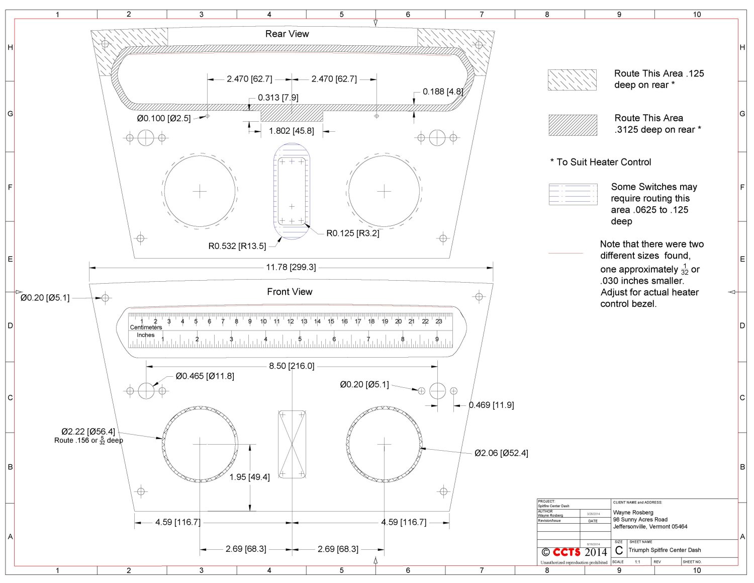
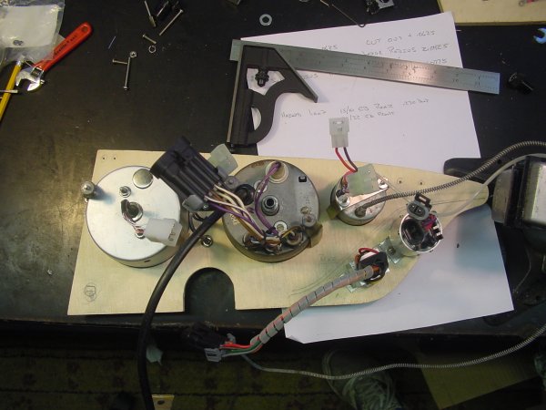
Center Dash Rear and Front View.
Click Here for a PDF of the stock center dash.
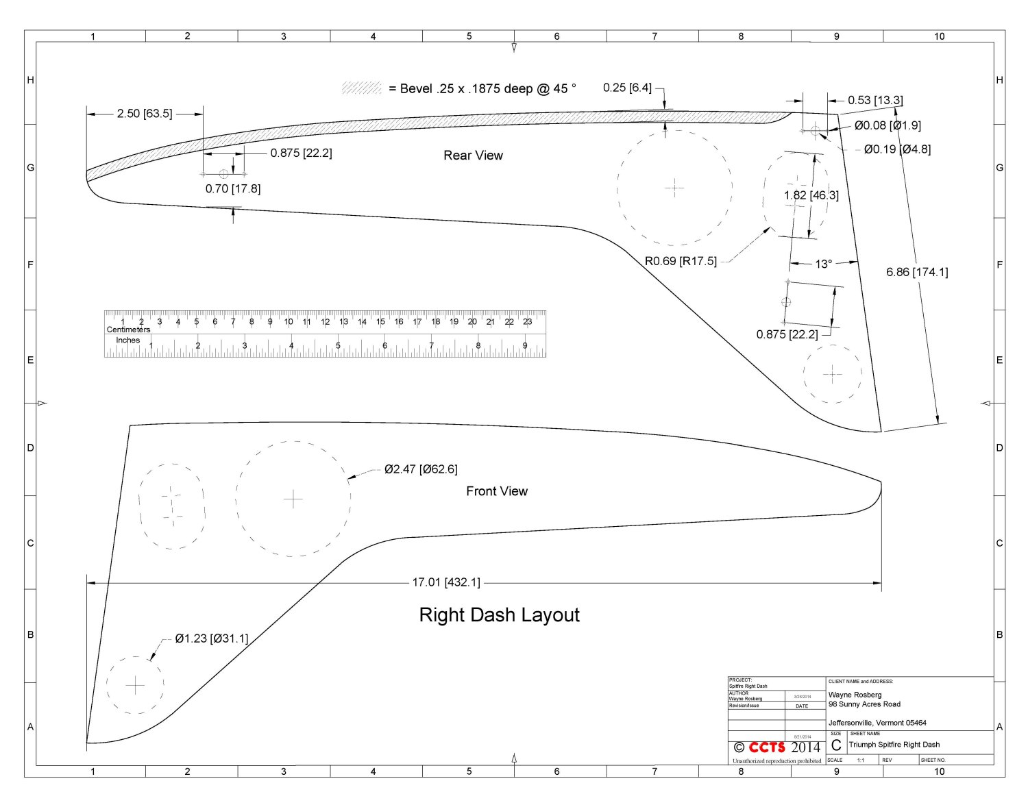
Right Dash front and rear views.
12-25-2014
Click Here for a PDF of the right dash.
Contact me if you want full size print outs or another file format.
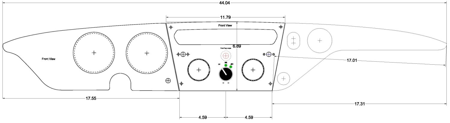
This is a conceptual mock up of the full dash as yet to be completed. I've not included switch and indicator positions in the left panel.
Please do not rely on the dimensions in this image.
Starting the layout of the new instrument panel(s).
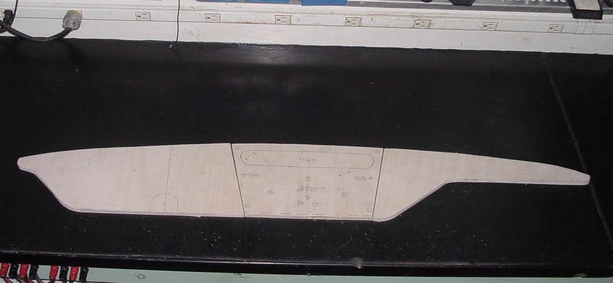
8-19-2014
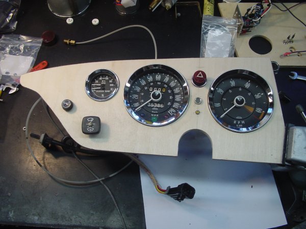
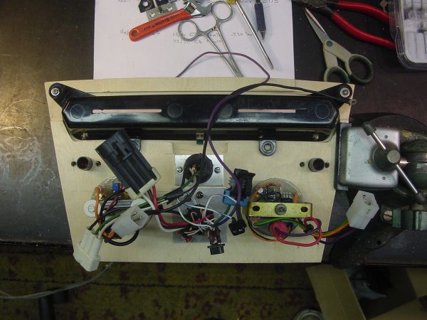
Fitting components to left panel. Images are before finish work and veneer. The speedometer case was refinished after this photo was taken.
The issue was not so much appearance, although it was a bit rusty, the paint was falling off inside and starting to get onto the face plate, dial, and into the mechanism.
It was bead blasted and re painted. Metallic foil tape was used to cover the slot originally used by the voltage stabilizer. The stabilizer is not required in this application
as the fuel gauge has its own stabilize and the temperature gauge is now mechanical. The tachometer has also been converted to a more modern electronic design.
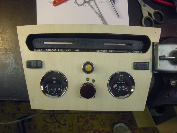
8-21-2014
Fitting components into the center panel. The headlight switch (round knob) is not attached in this photo and the heater control bezel is temporarily held with a couple small screws.
The yellow switch is fog lamps. More work to do before it is ready for veneer.
The center panel layout above does not reflect the head lamp switch modification. Stock layout is shown.
The two propped up together after nailing down the headlamp switch, more fine adjustment on the heater control bezel.... etc... etc... etc....
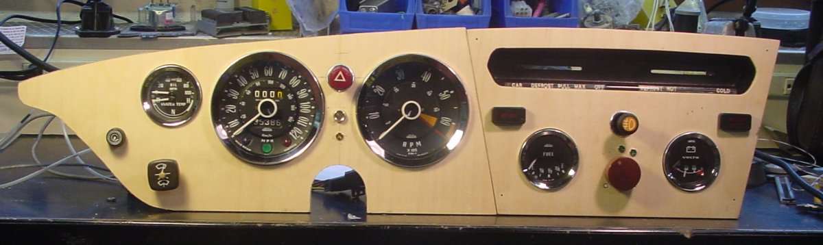
8-24-2014
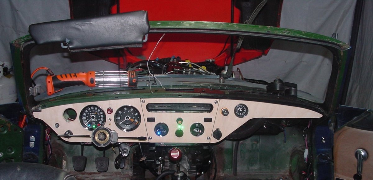
Trying to make things fit, and they do pretty well. Will need to set the dash pad in. Left panel needs some adjustment.. Everything so far works,
The led's on the headlamp switch are way too bright....... Will try to install the temperature / oil pressure gauge in the left panel tomorrow.
9-4-2014
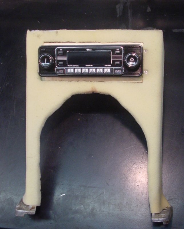
Made up an adaptor to fit the new radio to the dash support. Cleaned up the edges of the cut out in the milling machine. Then glued
two pieces of 8 ½ X 3½ X 3⁄8 hardwood plywood together. Routed the front piece to fit the cut out which is 7 1⁄2 X 2 7⁄8 X not quite ¼ inch thick.
The assembly was clamped into the milling machine and the hole for a DIN mount cut out.
Four 6-32 flat head screws were tapped into the support to hold this in place. Because the radio face plate folds down for removal and to load a CD, clearance
to the gear selector was an issue. With the radio mounted flush, the faceplate just clears the gear selector in second or fourth gear.
The photo shows the radio mounted and the start of covering the support piece. This is ¼ inch foam and will be vinyl covered to match the seats.


©CCTS 2001 -